Jeffrey's Log
Published on: January 19, 2014
If you haven’t installed Migen or don’t know about Migen, read my previous blog post Installing Migen – the Python based hardware description language
D flip-flops

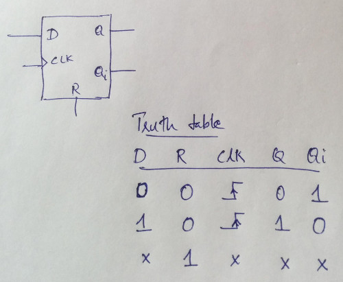
A D flip-flop spits the data out which is kept in the data input pin when the clock is applied(in positive edge or negative edge). The D flip-flop that we are going to design has the input pin D, output pins Q and Qi(inverted of Q). It also has a clock clock input and a reset pin which makes the flip-flop synchronous.
The D flip-flop shown over here is a positive edge triggered flip-flop. The truth table represents the mapping between the input pins to the output pins based on the reset pin and clock pin state. Since its a positive edge triggered flip-flop, the clock pin is shown as a transition from low to high.
Just for a reference, this is the datasheet of a D flip-flop IC.
A D flip-flop using Migen
Create a file named Dff.py and add this code to it.
from migen.fhdl.std import *

class Dflipflop(Module):
  def __init__(self, D, Q, Qi):
    self.sync += Q.eq(D)
    self.comb += Qi.eq(~Q)
Digital circuits can be divided into synchronous(i.e works based on the clock input) and asynchronous(independent of clock) circuits. Asynchronous circuits are also known as combinational logic. The Python syntax used for describing the D flip-flop can be more clearly understood by reading the Migen user guide. So I won’t be explaining here the syntax used. Only describing the synchronous and combinational(asynchronous) statements are in my scope.
self.sync += Q.eq(D)
Q.eq(D) equates/copies the content of D to Q which are the input and output of our flip-flop. This is then assigned as a synchronous using self.sync +=. As mentioned before, a D flip-flop copies the data from the input pin to the output pin in synchronous to the clock transition. Hence this circuit is a synchronous circuit.
self.comb += Qi.eq(~Q)
Qi.eq(~Q) is used to invert Q and copy to Qi. This is assigned as a combinational logic. This means Qi is independent of the clock. But out flip-flop is a synchronous. This doesn’t means that Qi will change asynchronously since the input of Qi is from a synchronous logic Q.
Testing the D flip-flop
Update your Dff.py with the below code.
from migen.fhdl.std import *
from migen.fhdl import verilog
from migen.sim.generic import Simulator, TopLevel
from random import randrange

class Dflipflop(Module):
  def __init__(self, D, Q, Qi):
    self.sync += Q.eq(D)
    self.comb += Qi.eq(~Q)

  def do_simulation(self,s):
    s.wr(D,randrange(2))

#Simulation and verilog conversion
D  = Signal()
Q  = Signal()
Qi = Signal()

#print(verilog.convert(Dflipflop(D, Q, Qi), ios={D,Q,Qi}))

sim = Simulator(Dflipflop(D,Q,Qi), TopLevel("Dff.vcd"))
sim.run(100)
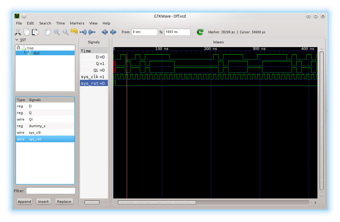
Execute this python script using the below command. This will generate a Dff.vcd which contains the test result. The vcd file can be viewed using GTKWave tool.
python3 Dff.py
gtkwave Dff.vcd

As I mentioned before, read the official Migen user guide and tutorial to understand what the code means.
To test the D flip-flop, we need to check if the input (D) is copied to the output(Q and also Qi). For this the input D should be fed with values(0 or 1). We can use the module random in Python to generate some random values.
s.wr(D,randrange(2))
The function randrange(2) generates a random number – either 0 or 1. s.wr writes the random number to D. The write happens only after the positive edge of the clock cycle.
Verilog equivalent of the D flip-flop
As I mentioned in my previous blog post (Installing Migen – the Python based hardware description language), Migen converts the Python code to equivalent Verilog code. Since the FPGA tools which we currently have only understands only Verilog/VHDL, this is required. The generated Verilog code can be loaded to your FPGA vendor’s software and verified on real hardware. Mibuild(a tool inside Migen) supports few FPGA vendors for which you don’t have to manually paste your Verilog code to the FPGA vendor’s software. Mibuild will do it for you(by accessing vendor tools via command line) and even it can load the bit stream file to FPGA. Usage of Mibuild will be explained later.
Uncomment the line in your Dff.py file and run the python code again. This line will print the Verilog equivalent code of our D flip-flop.
print(verilog.convert(Dflipflop(D, Q, Qi), ios={D,Q,Qi}))
Below is the Verilog output.
/* Machine-generated using Migen */
module top(
        input D,
        output reg Q,
        output Qi,
        input sys_clk,
        input sys_rst
);


// synthesis translate_off
reg dummy_s;
initial dummy_s <= 1'd0;
// synthesis translate_on
assign Qi = (~Q);

always @(posedge sys_clk) begin
        if (sys_rst) begin
                Q <= 1'd0;
        end else begin
                Q <= D;
        end
end

endmodule
Another way of testing D flip-flops: A frequency divider
Note: Below shown is not the right way to do a frequency division. This is just an example to show Migen’s testing capabilities.

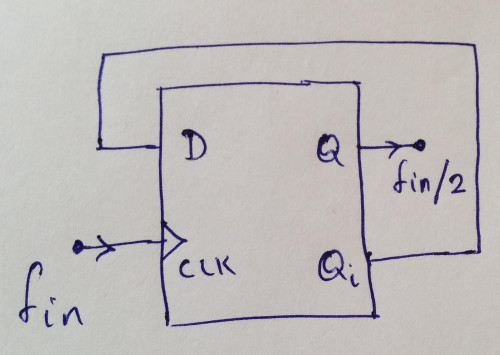
A D filp-flop can be used as a frequency divider (frequency / 2). Read this for a more clear explanation. Make a connection from Qi to D to divide the frequency(fed to the clock pin) by 2. Connecting a wire between pins is very easy in Migen - just use the same Signal() for both the pins.
Create a file named Dff_Divider.py and add the below code.
from migen.fhdl.std import *
from migen.fhdl import verilog
from migen.sim.generic import Simulator, TopLevel

class Dflipflop(Module):
  def __init__(self, D, Q, Qi):
    self.sync += Q.eq(D)
    self.comb += Qi.eq(~Q)

#Simulation and verilog conversion part
Connect = Signal()
Q = Signal()

sim = Simulator(Dflipflop(Connect,Q,Connect), TopLevel("Dff_Divider.vcd"))
sim.run(100)
Published on: January 17, 2014
Migen is a Python tool which helps you to describe hardware(like Verilog and VHDL) in Python langauge. Like a C compiler which converts C language to assembly, Migen converts Python code to Verilog/VHDL statements. Migen helps in describing hardware in a more Object-oriented manner which would be hard to realise in Verilog/VHDL. A free and open source project (https://github.com/m-labs/migen), Migen is also used for designing the SoC (MiSoc) of an open source hardware project Milkymist One.
Migen toolset contains the Migen itself, the Mibuild and the simulator. Migen converts the Python code to Verilog/VHDL. Mibuild is for converting the Verilog/VHDL code to bitstream file and transfering to the FPGA. If your FPGA is not supported by Mibuild, you can add support for it or you can paste your Verilog/VHDL code to your FPGA tool. The simulator just integrates Migen with Icarus Verilog for simulation. Simulation requires a test bench which is also written in Python. I will explain here how to install Migen and the simulator. Installing Mibuild will be done later(once I get my FPGA board).
Though there exist a tutorial about installing and using Migen, I faced some problems while installing in my Ubuntu machine which was not as per the tutorial. After reading this post, I would recommend to read the official tutorial from the Migen page. This will provide some more clarity. Also make sure to read this post complete before proceeding on your machine.
1) Make sure you have installed Python3, setuptool and git. On an Ubuntu machine this can be done using the below command
sudo apt-get install git python3 python3-setuptools
2) Get the Migen tool to your machine
git clone https://github.com/m-labs/migen.git
3) Move into Migen folder and install
cd migen
python3 setup.py install
Note: There is an option to use Migen – without installation! Just you need the project in your machine. Show the path to Python so that next time when you import Migen modules, Python will search those paths. For this you don’t need the python3-setuptools mentioned in Step 1. Clone the project to the machine using Step 2 and then run export PYTHONPATH=‘pwd‘/migen
Now the simulator installation. Once you are inside the Migen folder(cd migen), move into the vpi folder using cd vpi. We need to run the make file inside the vpi folder. But before that there are some more things to be done.
1) Install Icarus Verilog which is the actual simulator. Also the simulator generates a wave dump of the simulation which can be viewed using GTKWave.
sudo apt-get install verilog gtkwave
2) Run the following commands inside the vpi folder to install the Migen simulator.
make
sudo make install
You might get an error while running sudo make install. In my machine the error was
install: accessing ‘/usr/lib/ivl’: No such file or directory
This might be beacuse the path were Icarus Verilog is installed might be at a different location. A peak into the Makefile and also to the error can give you some hints on what to search for. I need to find where the ivl folder is. For that I used the find command find /usr/ -name ivl\*. I have to pass the new found path (/usr/lib/i386-linux-gnu/ivl) to the make install command. Run the following to install
sudo make install INSTDIR=/usr/lib/i386-linux-gnu/ivl/
Thats it! You have successfully installed Migen and its simulator.
There is another tutorial about Migen. Read it – Designing a D flip-flop using Migen
Published on: April 14, 2013
Recently I was not able to login to my wordpress account. If I visit my wp-login.php page, I was getting a 403 error. Initially I thought it was problem with my wordpress installation but it was not. The error was because of a brute force attack on the wordpress login pages. My server was blocking access to this page. Lot of people are facing this problem. So I thought of blogging. There are plugins to block this attack. But they can only be installed and activated once you are able to login.
Below is the solution for the wp-login.php issue which I found from internet. My initial target was to login. The quickest solution was to rename wp-login.php to a new file name and also replace with the new file name in the renamed wp-login.php file. In the following link, you will get the details how to do http://wordpress.org/support/topic/wp-loginphp-change-to-your-custom-url. This is not a recommended method but a quick solution to get a login.
Once you login, you can search for wordpress security plugins. Some restricts the number of login, some hides the login page. Search and install which one you found better. I am using Better WP Security. Once you enable your security plugin, I would suggest to revert back to file name wp-login.php and also replace inside the php file.
Happy blogging!
Published on: January 01, 2013
STM32F4DISCOVERY is an ARM Cortex M4 development kit.
I don’t plan to write again a toolchain setup instruction for this board. You can install toolchain and flash tool as per instructions provided in the below link
http://recursive-labs.com/blog/2012/05/07/stm32f4discovery-chibios-linux/ Read the section – Building the toolchain on Debian using “Summon Arm Toolchain”
While installing the toolchain I got an error zlib.h: No such file or directory. On a Debian system you can remove this error by issuing apt-get install zlib1g-dev
The ARM toolchain is build using summon-arm-toolchain script. This toolchain also installs a free GPL V3 based firmware library known as libopencm3.
As I mentioned above, the summon arm toolchain will also install libopencm3. libopencm3 generates some header files during installation. These header files needs python yaml support. The build might stop because of this. You can fix this issue by running apt-get install python-yaml
You can find examples for STM32F4DISCOVERY from https://github.com/libopencm3/libopencm3/tree/master/examples/stm32/f4/stm32f4-discovery
Additional link for reference
1) http://jeremyherbert.net/get/stm32f4_getting_started This link uses the examples from proprietary firmware library of ST.
Published on: November 26, 2012
I have seen many times people getting confused by the terms microcontroller and microprocessor. This blog post covers some basics which I know. I will try to explain the concepts in an simple manner. Please update corrections, feedbacks, suggestions etc in the comments field.
Microcontrollers are small computers which can do data processing. With this data processing capability, we can design embedded systems(computers) such as hand-held video games, mobile phones, etc. Usually these embedded devices uses a special range of microcontroller with a microprocessor called as ARM. There are other range of microcontrollers(known as AVR, PIC, MSP430 etc) with different microprocessors which will be discussed later.
Microcontrollers and microprocessors are different. Microprocessor is a device which can only do data manipulation. We need to pass data(or program) to the microprocessor, then it will process the data as we say and give it back. Microprocessors cannot store large programs because it doesn’t have large memories. They contains small memories called as registers which can only store small amount of data for data manipulation. This is a problem with microprocessors. We need extra hardware to store our programs. These extra hardwares are called as RAM(Random Access Memory), ROM(Read Only Memory), etc. After the microprocessors does the data manipulation, we need to view it on a screen(monitor). A microprocessors cannot write directly to a monitor. It needs again another special hardware called as display controller. Building an embedded system with these different hardwares is not easy since it involves some complexity because embedded system needs additional hardwares sensors, displays etc. Joining all these hardware is not an easy task. For this microcontrollers can help us.
But microcontrollers are different. In easy terms to say, microcontroller is a chip with microprocessor and its associated hardware (such as RAM, ROM, display drivers etc). So building embedded system with microcontrollers is easy.
If you want to understand more clearly about microcontrollers and microprocessors, go ahead reading this paragraph or else jump to next paragraph. Think about your computer. It has a monitor, keyboard, mouse, CPU, speakers etc. A computers CPU is the main part to which we connect the monitor, keyboard, mouse, etc. The computers CPU contains a processor (which might be an Intel Pentium4 or Intel Core i3 or an AMD Athlon), RAM (which is of 2GB or 8GB or of some other capacity), a hard disk to store data etc. If you know well about computers, you should know that a processor cannot do any work alone. It needs a RAM, hard disk etc. When you join them together, computers CPU will start to work. This is the same case with microcontrollers and microprocessors. You can imagine the processor(Intel Core i7 or AMD Athlon) as microprocessor and computers CPU completely(including hard disk, RAM, processor) as an microcontroller. With a processor alone we cannot do anything but with an CPU, we can connect a keyboard, mouse and a monitor to do our daily works. Hope you understood the difference between microprocessor and microcontroller.
There is no meaning in explaining more details about each peripherals. There are lot of tutorials existing in the Internet. I would recommend you to read those. My idea was to guide you to the world of computers. The main problem with engineers is that they know about computers but they don’t know about the internal working. If you want to know more about computers, go ahead reading the next paragraph. I would recommend this for all computer and electronics graduates.

Read the book The Elements of Computing Systems (From NAND to Tetris). This is an wonderful book which explains you how computers work from top to bottom i.e how microprocessors are made, how they interact with keyboard, monitor, etc, how an compiler works, how an operating system works etc. The most amazing part of this book is that it not only tells you how things work but also teaches you to write your own compiler, assembly programs, operating systems etc. Don’t worry. Its not a huge book. Try to get this book and read while you are traveling in bus or whenever you want.
I would recommend you not to miss this book. Reading this book alone will give you good knowledge. If you do the assignments in the book, its more wonderful and you can easily understand the computer systems. Please let me know your feedback after reading this awesome book!


